Injection molding is capable of producing very large volumes of parts with high consistency. However, even well-maintained molds can occasionally produce defects. One of the most common of these defects is flash.
Flash occurs when molten plastic escapes between mold surfaces during injection, forming thin unwanted material along parting lines, edges, or openings in the part.
In small quantities flash may be removed during secondary operations, but in many applications flash can interfere with assembly, product function, or cosmetic appearance.
In high-volume molding operations, detecting flash early is critical. If flash develops during a long production run and goes unnoticed, thousands of defective parts may be produced before the problem is discovered.
Automated inspection systems using machine vision can detect flash as parts are produced and remove defective parts from the production stream.
What Causes Flash in Injection Molding
Flash occurs when plastic is forced into gaps between mold surfaces. These gaps may develop for several reasons.
- worn mold parting surfaces
- excessive injection pressure
- mold misalignment
- contamination between mold faces
- damage to mold edges or inserts
Flash often appears along the parting line of the mold, but it may also occur around holes, slots, or threaded features.
Because flash forms as a thin raised edge on the surface of the part, it can often be detected visually when proper lighting and inspection methods are used.
Why Flash Is Difficult to Inspect Manually
Many molding operations still rely on operators to visually inspect parts for flash. A typical process involves removing parts from a bin or conveyor, examining the part edges, and sorting good parts from defective ones.
Manual inspection works in low-volume situations, but it becomes unreliable in high-speed production environments.
Operator fatigue can reduce inspection accuracy over time, especially during long shifts. Thin flash edges may be difficult to see, particularly on dark or glossy parts. In addition, production rates in modern molding operations can make it difficult for operators to keep up with part volumes.
For example, a 32-cavity mold operating on a 13-second cycle produces thousands of parts per hour. Under these conditions, manual inspection can easily miss defects.
Automated inspection systems allow every part to be evaluated consistently without depending on human attention.
Machine Vision Techniques for Detecting Flash
Machine vision systems detect flash by capturing images of the part and analyzing the shape of its edges and surfaces.
Several lighting and imaging techniques are commonly used.
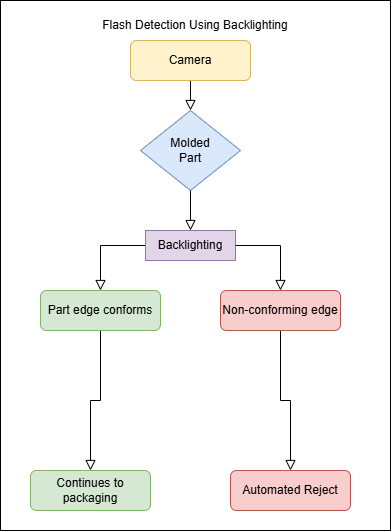
Backlighting
Backlighting is one of the most reliable methods for detecting flash on molded parts.
In a backlighting setup, the part is positioned between the camera and a bright light source. The camera captures the silhouette of the part, allowing the system to measure the outer profile of the component.
Flash appears as a thin extension beyond the expected part boundary.
By comparing the measured edge of the part to a reference profile, machine vision software can determine whether flash is present.
Dark Field Lighting
Dark field lighting is another common technique for detecting flash.
In this configuration, light is directed across the surface of the part at a shallow angle rather than directly from above.
Raised edges such as flash scatter light toward the camera, causing them to appear bright against a dark background. Flat surfaces remain relatively dark.
This approach is often effective for detecting small raised defects that may not be visible under direct illumination.
Part Handling Considerations
Successful inspection systems depend not only on cameras and lighting but also on how parts are presented to the inspection station.
Injection molded parts are typically ejected from the mold and fall onto conveyors or collection bins. During this process parts may rotate, tumble, or overlap.
To ensure reliable inspection, parts usually need to be singulated and presented consistently to the camera.
- vibratory feeders
- guided tracks that orient the part
- rolling inspection tracks for cylindrical parts
- multi-camera stations positioned around the part
Need Help Evaluating an Inspection Problem?
If your manufacturing process relies on manual inspection to detect flash or other defects, it may be possible to automate the process using machine vision and custom automation equipment.
You can contact Frogmouth Automation to discuss your application or send photos or video of the process for evaluation.